Discrete Element Method (DEM)#
In this guide, we summarize the theory behind DEM. For further details, we refer the reader to the article by Blais et al. [1] and the one by Golshan et al. [2]
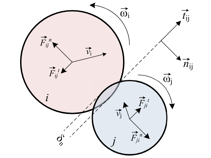
Where:
\(m_i\) mass of the particule i;
\(\mathbf{v_i}\) velocity of the particule i;
\(\mathcal C_i\) particles in contact list;
\(\mathbf{F}_{ij}^\mathrm{n}\) normal contact force due to the contact between particles i and j;
\(\mathbf{F}_{ij}^\mathrm{t}\) tangential contact force due to the contact between particles i and j;
\(\mathbf{g}\) gravitationnal acceleration;
\(\mathbf{F}_i^\mathrm{ext}\) external forces;
\(I_i\) moment of inertia of particle i;
\(\mathbf{\omega_i}\) angular velocity of particle i;
\(\mathbf{M}_{ij}^\mathrm{t}\) tangential friction torque due to the contact between particles i and j;
\(\mathbf{M}_{ij}^\mathrm{r}\) rolling friction torque due to the contact between particles i and j;
\(\mathbf{M}_i^\mathrm{ext}\) external torques;
Contact Force and Torque Models#
The normal and tangential contact forces use linear or nonlinear viscoelastic models and are calculated as followed:
Where:
\(\delta_{\mathrm{n}}\) normal overlap;
\(\mathbf{\delta_\mathrm{t}}\) tangential displacement vector;
\(\mathbf{n}_{ij}\) contact normal vector;
\(k_\mathrm{n}, k_\mathrm{t}\) spring constants;
\(\eta_\mathrm{n}, \eta_\mathrm{t}\) damping model constants;
\(\mathbf{v}_{rn}\) relative velocity in the normal direction;
\(\mathbf{v}_{tn}\) relative velocity in the tangential direction;

The contact normal vector \(\mathbf{n}_{ij}\) is computed as:
The normal overlap (\(\delta_{\mathrm{n}}\)) is the contact distance between the particles i and j. In the case of a collision between a particle and a wall, the wall is considered as j. The tangential displacement (\(\delta_\mathrm{t}\)) depends on the contact history and is updated during a contact. The normal and tangential displacements are calculated as follow:
Relative Velocities#
The relative velocities are calculated to update the tangential displacement and for their contribution in the force models:
Spring and damping constants#
The spring and damping constants for the linear and nonlinear viscoelastic models are calculated as follows:
Parameters |
Linear model definitions |
Nonlinear viscoelastic model definitions [3] |
|---|---|---|
Normal spring constant |
\(k_\mathrm{n} = \frac{16}{15}\sqrt{R_{\mathrm{e}}}Y_{e}\left(\frac{15m_{e}V^2}{16\sqrt{R_{\mathrm{e}}}Y_{e}}\right)^{0.2}\) |
\(k_\mathrm{n} = \frac{4}{3}Y_{e}\sqrt{R_{\mathrm{e}}\delta_{\mathrm{n}}}\) |
Normal damping model constant |
\(\eta_\mathrm{n} = -2\beta\sqrt{m_{e} k_\mathrm{n}}\) |
\(\eta_\mathrm{n} = -2\sqrt{\frac{5}{6}}\beta\sqrt{S_\mathrm{n}m_{e}}\) |
Tangential spring constant |
\(k_\mathrm{t} = 0.4 k_\mathrm{n}\) |
\(k_\mathrm{t} = 8G_{e}\sqrt{R_{\mathrm{e}}\delta_{\mathrm{n}}}\) |
Tangential damping model constant |
\(\eta_\mathrm{t} = -2\beta\sqrt{m_{e} k_\mathrm{t}}\) |
\(\eta_\mathrm{t} = -2\sqrt{\frac{5}{6}}\beta\sqrt{S_\mathrm{t}m_{e}}\) |
Where:
\(R_{\mathrm{e}}\) effective radius;
\(Y_\mathrm{e}\) effective Young’s modulus;
\(m_\mathrm{e}\) effective mass;
\(V\) characteristic impact velocity, this parameters is set to 1.0;
\(e\) coefficient of restitution;
\(G_\mathrm{e}\) effective shear modulus;
These parameters are computed as follows:
Where:
\(\nu_i, \nu_j\) poisson coefficient of particle i or j;
Coulomb’s limit#
Coulomb’s criterion is breached when the following condition is broken during a collision:
A breach means the collision is having gross sliding and tangential force needs to be limited to the Coulomb’s limit. To do so, the tangential displacement \(\mathbf{\delta_\mathrm{t}}\) is first limited and then the tangential force is recalculated.
When using nonlinear viscoelastic contact model, the tangential displacement is computed from tangential spring force :
Regarding the particle-wall contacts, the applied models are the same as for particle-particle contacts.
Note
When using a cohesive force model, Coulomb’s criterion needs to be modified. For further information on cohesive force models, see Cohesive force models .
Tangential torque#
Tangential torque is the torque generated by the tangential force. It can be calculated through:
Note
As of now, the lethe-particles solver only uses spherical particles, thus the normal force does not generate a torque on the particle during a collision.
Rolling friction models#
Rolling friction may be computed through a constant torque model, a viscous torque model or an elastic-plastic spring-dashpot torque model. It is also possible to ignore the rolling resistance by using the no-resistance model. The corresponding models are described by the following equations:
Models |
Equations |
|---|---|
Constant resistance |
\(\mathbf{M}_{\mathrm{r},ij} = -\mu_\mathrm{r}R_{\mathrm{e}}|\mathbf{F}_{\mathrm{n},ij}| \mathbf{\hat{\omega}}_{ij}\) |
Viscous resistance |
\(\mathbf{M}_{\mathrm{r},ij} = -\mu_\mathrm{r}R_{\mathrm{e}}|\mathbf{F}_{\mathrm{n},ij}||\mathbf{V}_{\omega}| \mathbf{\hat{\omega}}_{ij}\) |
Elastic-plastic spring-dashpot resistance |
\(\mathbf{M}_{\mathrm{r},ij} = \mathbf{M}_{\mathrm{t+\Delta t}}^{k} + \mathbf{M}_{\mathrm{t+\Delta t}}^{d}\) |
No resistance |
\(\mathbf{M}_{\mathrm{r},ij} = 0\) |
Where:
\(\mu_\mathrm{r}\) rolling friction coefficient;
\(\hat{\omega}_{ij}\) relative angular velocity;
\(V_{\omega}\) contact point relative velocity caused by the angular velocities;
\(\mathbf{M}_{\mathrm{r,t+\Delta t}}^{k}\) elastic resistance torque at the end of the current time step;
\(\mathbf{M}_{\mathrm{r,t+\Delta t}}^{d}\) viscous damping resistance torque at the end of the current time step;
The parameters for the constant and viscous models are computed as follows:
For the elastic-plastic spring-dashpot model, \(\mathbf{M}_{\mathrm{r}}^{k}\) and \(\mathbf{M}_{\mathrm{r}}^{d}\) are computed using the following algorithm:
Where:
\(\mathbf{\omega}_{ji}\) relative angular velocity between particle j and i;
\(\mathbf{\omega}_{ji,t}\) relative angular velocity between particle j and i perpendicular to the normal contact vector (vector in the contact plane);
\(\mathbf{\Delta\theta}\) incremental relative rotation between particle j and i;
\(k_\mathrm{r}\) rolling stiffness;
\(\mathbf{\Delta M}_{r,t}^\mathrm{k}\) incremental elastic rolling resistance torque;
\(M\mathrm{^{m}_{r}}\) limiting spring torque which is achieved at a full angular mobilisation;
\(I_\mathrm{e}\) effective inertia;
\(C_\mathrm{r}^{\mathrm{crit}}\) rolling critical viscous damping constant;
\(C_\mathrm{r}\) rolling viscous damping constant;
\(f\) full mobilisation model parameter;
\(\mathbf{M}_{t}^{\mathrm{k}}\) starts at \(\mathbf{0}\) at the beginning of a contact and is set back to \(\mathbf{0}\) when the contact ends. \(\mathbf{M}_{\mathrm{r},ij}\) is applied on particle i. The rolling resistance torque applied on particle j can be found using Newton’s Third Law.
For further details on all three rolling resistance model, we refer the reader to the article by Ai et al. [4]
Cohesive force models#
Lethe supports two cohesive force models: the Johnson-Kendall-Roberts (JKR) and the Derjaguin-Muller-Toporov (DMT). Both models describe attractive forces due to van der Waals effects. Choosing the right model can be based on the Tabor parameter \(\mathbf{\tau}\) which represents the ratio between the normal elastic deformation caused by adhesion and the distance at which adhesion forces occur. [5]
This parameter can be described as:
Where \(\mathbf{z_{\mathrm{o}}}\) is the equilibrium separation of the surfaces and \(\mathbf{\gamma}_\mathrm{e}\) the effective surface energy. The DMT model is applicable for low \(\mathbf{\tau}\) values (\(\mathbf{\tau} < 1\)) while the JKR model is more appropriate for high \(\mathbf{\tau}\) values (\(\mathbf{\tau} > 1\)) . In essence, the DMT model is preferred for small, hard particles (high \(Y\)) and the JKR model for large, soft particles.
Johnson-Kendall-Roberts force model#
The Johnson-Kendall-Roberts (JKR) model describes attractive forces due to van der Waals effects. [6] This model modifies the Hertz formulation by defining a larger contact path radius (\(\mathbf{a}\)) and by taking into account the effective surface energy (\(\mathbf{\gamma}_{e}\)). The model is defined by:
Where \(\mathbf{F_{n}^\mathrm{JKR}}\) corresponds to the normal spring force and attractive force combined and \(\mathbf{\gamma_{\mathrm{e}}}\) is the effective surface energy. Note that if the effective surface energy is equal to zero, the JKR model reverts to Hertz model.
The effective surface energy can be computed as:
Where \(\gamma_{i}\) and \(\gamma_{j}\) are the surface energy of each material (particle or wall) and where \(\gamma_{i,j}\) is the interface energy which is equal to zero when both surfaces are the same material. The interface energy term is approximated using [7]:
To compute the \(\mathbf{F_{n}^{JKR}}\), the contact patch radius needs to be determined. The contact patch radius can be related to the normal overlap as follows:
This equation can be rewritten as a fourth-order polynomial function with two complex and two real roots.
Since we are always solving for the same real root, a straightforward procedure, described by Parteli et al. can be used [8]:
Finally, the \(\mathbf{F_{\mathrm{n}}^{JKR}}\) can be computed as follows:
The normal damping, tangential damping and tangential spring constants need to be computed using the same procedure as the nonlinear model.
A simplified version of the JKR model (SJKR-A) is implemented in Lethe. Please refer to C. J. Coetzee and O. C. Scheffler for more information on the different versions of the JKR model and their specific features [6].
A modified Coulomb’s limit, based on the work of C. Thornton [9], is used for the JKR model. Using the usual limit can result in permanent slip since the total normal force can be equal to zero even when there is a substantial overlap between particles.
The modified Coulomb’s criterion is breached when the following condition is broken during a collision:
Where \(\mathbf{F_{\mathrm{po}}}\) is the pull-off force, which can be computed as follows:
Derjaguin-Muller-Toporov force model#
The Derjaguin-Muller-Toporov (DMT) model describes attractive forces due to van der Waals effects. This model is more suitable for particles with smaller diameter, lower surface energy and higher Young’s modulus. In Lethe, the DMT model is implemented following the work of Meier et al. [10]. This implementation includes non-contact forces between particles. The model is described by the following equations:
where \(A\) is the Hamaker constant which is used to quantify the strength of van der Waals forces. \(\delta_{\mathrm{o}}\) represents the distance at which the van der Waals force curve equals the pull-off force \(F_{\mathrm{po}}\) and \(\delta^*\) represents a cut-off radius at which the van der Waals has a relative decline of \(C_{\mathrm{FPO}}\) [10]. They are computed using:
where \(C_{\mathrm{FPO}}\) is a user parameter used to determined the cut-off distance at which the non-contact forces are being performed.
The Coulomb’s limit threshold for the DMT model is computed in the same way as for the non-linear viscoelastic model. This means that the adhesion force term is not taken into account when computing the norm of the normal force. For further information, see Coulomb’s limit .
Integration Methods#
Two types of integration methods are implemented in Lethe-DEM:
Explicit Euler method;
Velocity Verlet method
Explicit Euler method is calculated as:
And velocity Verlet method is calculated with half-step velocity as:
Thermal DEM in a Stagnant Gas#
- The heat transfer mechanisms considered are:
Conduction through the particles themselves
Conduction between particles through the contact surface (microcontacts and macrocontacts)
Conduction through the interstitial fluid (microgap and macrogap between particles)
The solid microcontacts and gas-filled microgaps allow to take into account the roughness of the particles. Instead of being considered smooth, the particles can have microscopic asperities on their surfaces, which affect conduction.
- Hypotheses:
The temperature is uniform within each particle.
The temperature of each particle changes slowly enough that thermal disturbances do not propagate beyond immediate neighbors.
Convection and radiation are neglected.
The interstitial fluid is a stagnant gas (usually air), through which conduction occurs for contacting particles.
The temperature of each particle i is computed as:
where \(Q_i \approx \sum Q_{ij} + Q_{Si}\) is the total rate of heat transferred to particle i, \(Q_{ij}\) is the rate of heat transferred between particles i and j, \(Q_{Si}\) is a potential source term applied to particle i and \(H_{ij}\) is the thermal conductance between particles i and j.
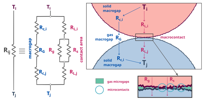
The thermal conductance, which is the inverse of the thermal resistance \(R_{ij}\), is calculated as follows by Beaulieu et al. [12]:
Where:
\(R_L\) resistance of the contact surface [11]
\(R_s\) resistance of the microcontacts [13]
\(R_g\) resistance of the interstitial gas microgap [14]
\(R_c\) resistance of the solid layers of the particles [12]
\(R_G\) resistance of the interstitial gas macrogap [14]

Modeling Heat transfer between two rough particles in contact. Adapted from [12].#
Thermal Resistances#
The thermal resistances, which model the heat transfer between particles are calculated as follows:
The contact radius \(r_c\) is calculated as follows:
The Young’s modulus in the simulation can sometimes be underestimated for computational efficiency and that can cause the contact radius and the overlap to be overestimated. To correct the contact radius, a factor c introduced by Zhou et al. [15] is used:
The parameters used to calculate the resistances are summed up in the following table:
Parameter |
Notation |
Definition |
|---|---|---|
Characteristic area (perpendicular to heat flux) |
\(A_i\) |
\(\pi(r_i^2 - r_c^2)\) |
Characteristic length (parallel to heat flux) |
\(L_i\) |
\(\frac{\pi r_i}{4}\) |
Harmonic mean thermal conductivity |
\(k_h\) |
\(\frac{2k_i k_j}{k_i + k_j}\) |
Effective microhardness |
\(H'\) |
\(\frac{2H_i H_j}{H_i + H_j}\) |
Effective radius |
\(R_{\mathrm{e}} = \frac{1}{2} \, r_h\) |
\(\frac{r_i r_j}{r_i + r_j}\) |
Effective Young’s modulus |
\(Y_\mathrm{e}\) |
\(\left( \frac{(1 - \nu_i^2)}{E_i} + \frac{(1 - \nu_j^2)}{E_j} \right)^{-1}\) |
Equivalent surface roughness |
\(\sigma\) |
\(\sqrt{\sigma_i^2 + \sigma_j^2}\) |
Equivalent surface slope |
\(\tau\) |
\(\sqrt{\tau_i^2 + \tau_j^2}\) |
Maximum Hertzian contact pressure |
\(P_0\) |
\(\frac{2Y_\mathrm{e} \delta_n}{\pi r_c}\) |
Error parameter 1 |
\(a_1\) |
\(\operatorname{erfc}^{-1}(2P_0/H')\) |
Error parameter 2 |
\(a_2\) |
\(\operatorname{erfc}^{-1}(0.03P_0/H') - a_1\) |
Thermal accommodation coefficients |
\(\alpha_{T_i}, \, \alpha_{T_j}\) |
values depend on the particles and gas |
Gas specific heats ratio |
\(\gamma_g\) |
value depends on the gas |
Gas thermal conductivity |
\(k_g\) |
value depends on the gas |
Gas molecular mean free path |
\(\Lambda\) |
value depends on the gas |
Gas Prandtl number |
\(Pr\) |
\(\frac{\mu_g c_g}{k_g}\) |
Gas parameter |
\(M\) |
\(\left( \frac{2 - \alpha_{T_i}}{\alpha_{T_i}} + \frac{2 - \alpha_{T_j}}{\alpha_{T_j}} \right)\left( \frac{2 \gamma_g}{1 + \gamma_g} \right)\frac{\Lambda}{Pr}\) |
Gas parameter |
\(S\) |
\(2\left(r_h - \frac{r_c^2}{2r_h}\right) + M\) |
Geometrical parameter |
\(A\) |
\(2\sqrt{r_h^2 - r_c^2}\) |
Geometrical parameter |
\(B\) |
\(0\) (for simple cubic packing) |
Particle-wall Resistances#
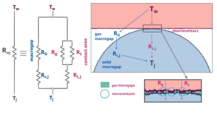
For particle-wall contacts, conduction is mostly computed the same way, except for minor differences. For the macrocontact and the solid layers resistances, they are only considered for the particle. In the same way, the interstitial gas macrogap resistance is halved as there is only a macrogap around the particle and not the wall.
As the radius of the wall can be seen as infinite, \(r_h\) and \(R_{\mathrm{e}}\) are taken equal to \(2r_j\) and \(r_j\) respectively.

Modeling Heat transfer between a rough wall and rough particle in contact.#