Mesh#
This subsection provides information of the simulation geometry and its mesh. The simulation geometry shape and size, number of refinements and other required information can be provided here. It should be mentioned that meshes from gmsh can also be defined in this section by setting type = gmsh.
subsection mesh
  # Type of mesh. Choices are <gmsh|dealii|lethe>
  set type = dealii

  # GMSH file name
  set file name = none

  # Grid arguments for dealii and lethe grids.
  set grid type      = hyper_cube
  set grid arguments = -1 : 1 : false

  # Initial refinement of the mesh
  set initial refinement = 0

  # Initial refinement of the mesh near user-specified boundaries
  set initial boundary refinement = 0

  # List of boundaries next to which the mesh should be refined. The list must contain integers separated by commas.
  set boundaries refined = 0, 1

  # Enable initial refinement until target size is reached
  set enable target size = false
  set target size        = 1

  # Indicates that the mesh is a simplex mesh
  set simplex = false

  # DEM-specific mesh parameters

  # Enables checking the input grid for diamond-shaped cells
  set check diamond cells = false

  # Enables adding the boundary neighbor cells of boundary cells to the particle-wall contact search list
  set expand particle-wall contact search = false

  # Mesh modification parameters

  # Translation to apply to the mesh
  set initial translation = 0, 0, 0

  # Rotation to apply to the mesh
  set initial rotation axis  = 1, 0, 0
  set initial rotation angle = 0

  # Mesh scaling factor
  set scale = 1
end
- The following choices for the mesh
typeare available: gmsh: if this type is chosen, a.mshfile generated from GMSH can be used. In this case, the grid file name must be specified in thefile namevariable.dealii: if this type is chosen, the deal.II grid generator class can be used. For additional documentation on these grids, you can consult the deal.II documentation for the GridGenerator . The type of grid is specified by thegrid typeparameter and the arguments used for grid generation by thegrid argumentsparameter.lethe: if this type is chosen, the grid will be generated by Lethe built-in mesh. These custom meshes are generally used for benchmark problems and are constructed using deal.II meshing tools. The type of grid is specified by thegrid typeparameter and the arguments used for grid generation by thegrid argumentsparameter.
- The following choices for the mesh
The following
lethebuilt-in mesh types, defined by thegrid typeparameter, can be generated:
Name |
Geometry |
|---|---|
|
|
|
|
|
|
|
|
|
|
|
|
|
|
|
|
|
The
initial refinementnumber determines the number of refinements the grid will undergo in the simulation before the simulation is run. This allows one to refine a coarse grid automatically. By default, most deal.II grids will be as coarse as possible and need to be refined. This is a desirable behavior for parallel simulations, since for quad/hex meshes, the coarsest level of the grid is shared amongst all cores. Consequently, using a coarse grid with too many cells will lead to a prohibitive memory consumption.The
initial boundary refinementdetermines the number of refinements the grid will undergo in the simulation in the vicinities of the boundary specified by theboundaries refinedparameter.The
enable target sizeandtarget sizerespectively enable and provide a maximal target size that initial refinement cycles must lead towards, in contrast to the more common way of specifying the number of refinement cycles to apply.Note
Like
initial refinementandinitial boundary refinement, the refinement until the target size is only applied when starting a new simulation. It is skipped when restarting from a checkpoint, since the triangulation stored in the checkpoint already carries its refinement.The
check diamond cellsandexpand particle-wall contact searchare parameters used in particles simulations. The former is used to verify the quality of the background mesh; detecting diamond cells is important as they should be avoided. The latter serves a purpose in contact detection when the background mesh is concave.simplex. If simplex is set to true, it indicates that the mesh being read is made of only simplex elements. If the mesh is oftype = dealiiit will be converted from a quad/hex mesh to a simplex mesh. If the mesh is oftype = gsmh, it will be read from a file as long as it is only made of simplices.The
initial translationparameter provides a way to move the mesh in space prior to simulating the problem. It can be useful when space-dependent functions are used, but that generating a translated mesh is inconvenient or impossible.The
initial rotation axisandinitial rotation angleparameters provide another way to move the mesh prior to simulating the problem.Attention
If the mesh is defined in a 2D space,
initial rotation axisis ignored and the mesh rotates counter-clockwise around the origin of the coordinate system according toinitial rotation angle.The
scaleparameter is used to scale the mesh. This is useful when the mesh is made in a different set of unit than what is desired by the simulation.Warning
When scale, translation and rotation are used together, the scaling is applied first, then the rotation, then the translation.
Warning
dealiiandlethegrids may carry curved manifolds. Scaling moves the vertices of the mesh, but not the manifolds attached to it, which can distort the geometry when the mesh is refined. Lethe prints a warning when a scaling factor is applied to such a grid. In that case, the geometry should preferably be dimensioned through thegrid argumentsinstead.
Lethe Grid Generators#
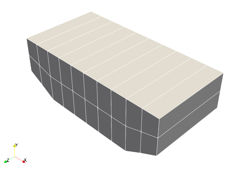
Periodic Hills#
subsection mesh
  set type            = lethe
  set grid type       = periodic_hills
  # Grid arguments for 2D case
  set grid arguments  = spacing_y : alpha : repetitions_x : repetitions_y
  # Grid arguments for 3D case
  set grid arguments  = spacing_y : alpha : repetitions_x : repetitions_y : repetitions_z
If this grid type is chosen, a mesh for the periodic hills CFD benchmark is created. For more details on this type of mesh and its grid arguments, refer to Flow over Periodic Hills.
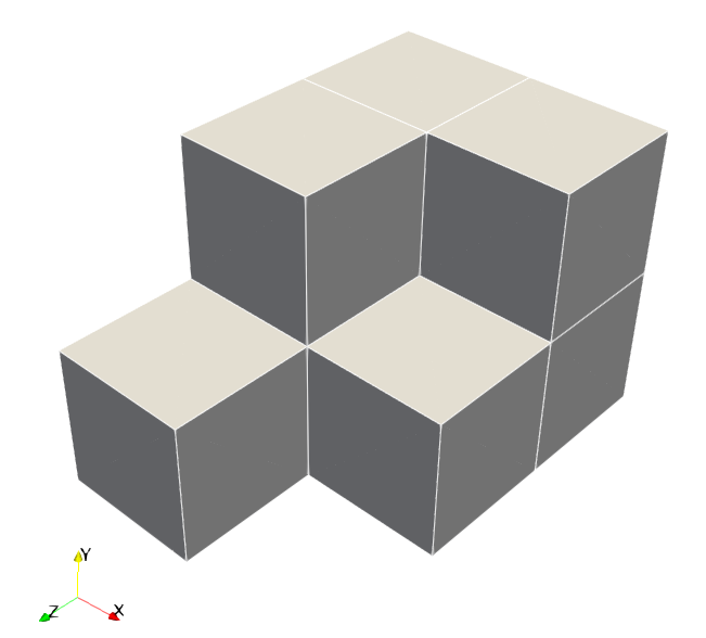
Fichera Oven#
subsection mesh
  set type            = lethe
  set grid type       = fichera_oven
  set grid arguments  = bottom_left : top_right : colorize
If this grid type is chosen, a mesh for the Fichera oven time-harmonic Maxwell benchmark is created. For more details on this type of mesh, refer to Fichera Oven.
The grid arguments accepts up to three colon-separated values as listed above.
The first two fields are required, where
bottom_leftandtop_rightarex,y,zcoordinates defining the bounding box of the mesh. They follow deal.II’s convention for a hyper rectangle, where the bottom left corner is the point with the smallest coordinates in each direction, and the top right corner is the point with the largest coordinates in each direction.The last field is optional, where
colorizeis a boolean that applies the following boundary ID convention: 0 for all the oven walls, 1 for the waveguide inlet which is the furthest face from the bottom_left corner with the normal pointing in the positive z direction.
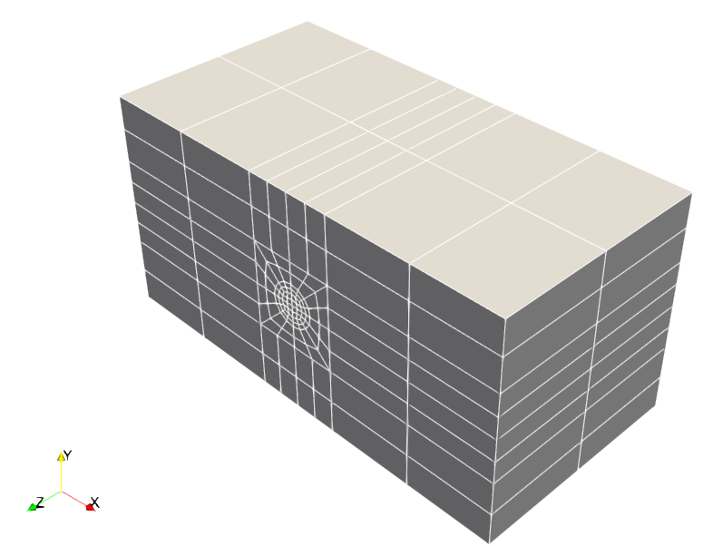
Uniform Channel with Meshed Cylinder#
subsection mesh
  set type            = lethe
  set grid type       = uniform_channel_with_meshed_cylinder
  set grid arguments  = bottom_left : top_right : center : inner_radius : outer_radius : pad_bottom : pad_top : pad_left : pad_right : height : n_slices : use_transfinite_region : mesh_obstacle : colorize
If this grid type is chosen, a mesh for a channel (similar to the deal.II uniform_channel_with_cylinder) is created.
The difference is the cylinder in the channel is meshed enabling the calculation of fields inside the cylinder which is useful for multiphysics simulations.
The grid arguments accepts up to fourteen colon-separated values as listed above.
The first five fields are required, where
bottom_left,top_right, andcenterarex,ycoordinates, andinner_radiusandouter_radiusare real numbers defining the cylinder and transition radii.The next four optional integer values (defaulting to
0) arepad_bottom,pad_top,pad_left, andpad_right, which control the number of cells in each padding direction.In 3D,
height(default1.0) sets the extrusion height andn_slices(default and minimum2) sets the number of layers in the \(z\) direction.- The last 3 parameters are boolean:
use_transfinite_region,mesh_obstacleandcolorizewhich are by default all set tofalse. use_transfinite_regionis use to enable the use of transfinite interpolation for the transition region between the inner and outer radii.mesh_obstacleis used to indicate whether the obstacle is meshed and given a material ID for the solid region or if the obstacle is not meshed and a new boundary is created.colorizeapplies the following boundary ID convention: 0 for the obstacle (if not meshed), then follows the deal.IIsubdivided_hyper_rectangleconvention for the outer boundaries but shifted by +1 for all of them to accommodate the obstacle boundary ID.
- The last 3 parameters are boolean:
Note
If the obstacle is meshed, the boundary IDs follow the standard deal.II convention for a subdivided hyper rectangle: 0 for left (-x), 1 for right (+x), 2 for bottom (-y), and 3 for top (+y), if 3D, 4 for front (-z) and 5 for back (+z).
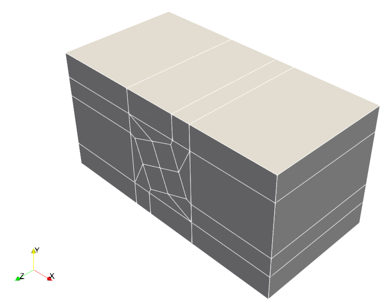
Uniform Channel with Meshed Square Prism#
subsection mesh
  set type            = lethe
  set grid type       = uniform_channel_with_meshed_square_prism
  set grid arguments  = bottom_left : top_right : center : inner_half_side : outer_half_side : rotation_deg : pad_bottom : pad_top : pad_left : pad_right : height : n_slices : mesh_obstacle : colorize
This mesh follows the same channel-and-padding concept as uniform_channel_with_meshed_cylinder, but replaces the circular obstacle by a square prism and adds an in-plane obstacle rotation.
The grid arguments accepts up fourteen colon-separated values as listed above.
As in the cylinder case,
bottom_left,top_right, andcenterarex,ycoordinates, the padding parameters are optional integers with default0, and the 3D extrusion parameters areheight(default1.0) andn_slices(default and minimum2).The square-specific geometric fields are
inner_half_sideandouter_half_side(instead of radii), androtation_degis an optional angle in degrees (default0) that rotates the inner square region.- The last 2 parameters are boolean:
mesh_obstacleandcolorizewhich are by default all set tofalse. mesh_obstacleis used to indicate whether the obstacle is meshed and given a material ID for the solid region or if the obstacle is not meshed and a new boundary is created.colorizeapplies the following boundary ID convention: 0 for the obstacle (if not meshed), then follows the deal.IIsubdivided_hyper_rectangleconvention for the outer boundaries but shifted by +1 for all of them to accommodate the obstacle boundary ID.
- The last 2 parameters are boolean:
Note
If the obstacle is meshed, the boundary IDs follow the standard deal.II convention for a subdivided hyper rectangle: 0 for left (-x), 1 for right (+x), 2 for bottom (-y), and 3 for top (+y), if 3D, 4 for front (-z) and 5 for back (+z).
Birmingham Fluidized Bed#
subsection mesh
  set type            = lethe
  set grid type       = birmingham_fluidized_bed
  set grid arguments  = enable_chimney : inlet_offset
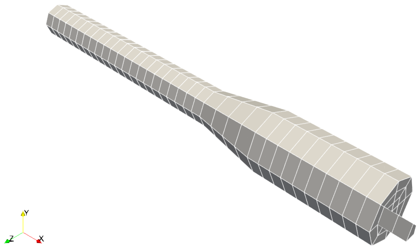
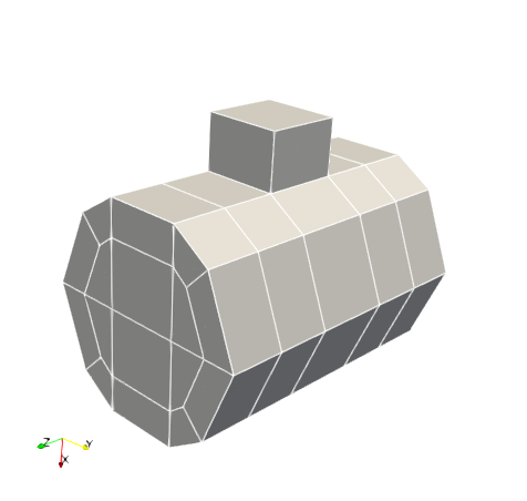
If this grid type is chosen a 3D mesh for the Birmingham fluidized bed geometry is created. The geometry is taken from Fede et al. (2016). The mesh is composed of a bottom cylinder (radius 0.077 m), a truncated cone, and a top cylinder (radius 0.127 m) joined along the x-axis. An optional rectangular chimney pipe can be attached to an off-center cell on the top end cap to serve as the outlet.
The grid arguments accepts two colon-separated values as mentioned above.
enable_chimneyistrueorfalseto enable or disable the chimney (defaults totrue)inlet_offsetis a positive real number (in meters) that extends the bottom cylinder into negative x, so that the original geometry starts at x = 0 regardless of the offset (defaults to0)
Boundary IDs are: 0 for walls, 1 for the inlet (x = -inlet_offset), and 2 for the outlet.
Impinging Jet Mixer#
subsection mesh
  set type            = lethe
  set grid type       = impinging_jet_mixer
  set grid arguments  = R_chamber : r_inlet : r_outlet : H_chamber : L_cone : L_outlet : L_inlet : z_inlet
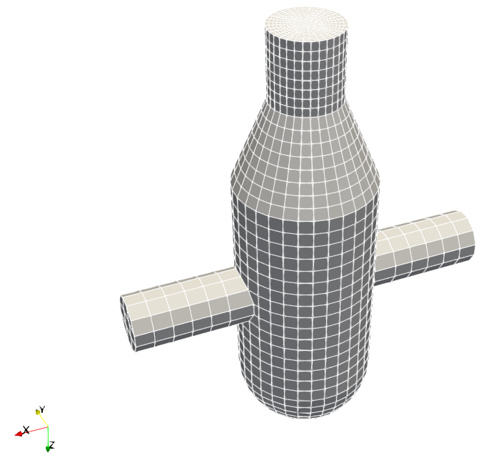
If this grid type is chosen a 3D mesh for an impinging-jet mixer is created. The geometry (mixing-chamber axis aligned with \(z\)) consists of a vertical cylindrical mixing chamber closed at the top by a hemispherical dome, a conical reduction followed by a straight outlet pipe below the chamber, and two opposing horizontal inlet pipes entering the chamber side wall from \(+x\) and \(-x\). The two inlet pipes share a common axis, and the mesh is datumed so that this axis lies on the \(z = 0\) plane (the plane where the opposing jets impinge).
The grid arguments accepts either an empty string (which uses the default dimensions) or exactly eight colon-separated dimensions (all in meters), in the order listed above.
R_chamberis the chamber radiusr_inletandr_outletare the inlet- and outlet-pipe radiiH_chamberis the chamber heightL_coneis the axial length of the conical reductionL_outletis the length of the straight outlet pipeL_inletis the length of each inlet pipez_inletis the height of the inlet axis above the chamber floor (which must satisfy \(0 < z_\text{inlet} < H_\text{chamber}\))
The default dimensions are 0.05 : 0.02 : 0.025 : 0.16 : 0.06 : 0.05 : 0.08 : 0.08. The mesh discretisation is not exposed and is fixed internally.
Boundary IDs are: 0 for the \(+x\) inlet, 1 for the \(-x\) inlet, 2 for the outlet, and 3 for all walls.
Cylinder#
subsection mesh
  set type            = lethe
  # Cylinder type. Choices are <cylinder_classic | cylinder_balanced | cylinder_squared | cylinder_regularized>
  set grid type       = cylinder_classic
  set grid arguments  = x_subdivisions : radius : half_length
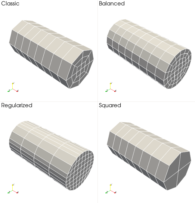
If this grid type is chosen, one of the following grid type options must be declared : cylinder_classic | cylinder_balanced | cylinder_squared | cylinder_regularized.
The cylinder_classic type is equivalent to a subdivided cylinder from deal.II and grid arguments must follow their related deal.II documentation for a cylinder .
The other cylinder types follow the same grid arguments:
x_subdivisionsis the number of cells to generate in the x directionradiusis the radius of the circle in the yz-planehalf_lengthis the half-length of the cylinder in the x direction
Warning
The squared cylinder may eventually leads to ill-posed jacobian transformation. As said in the deal.II documentation : “The four cells that were originally the corners of a square will give you some troubles during computations, as the jacobian of the transformation from the reference cell to those cells will go to zero, affecting the error constants of the finite element estimates”. This type of mesh is available, but its usage is not recommended.
Merged Cube#
subsection mesh
  set type            = lethe
  set grid type       = cube_merged
  set grid arguments  = R_cylinder : L_plate : H : n_subdivisions
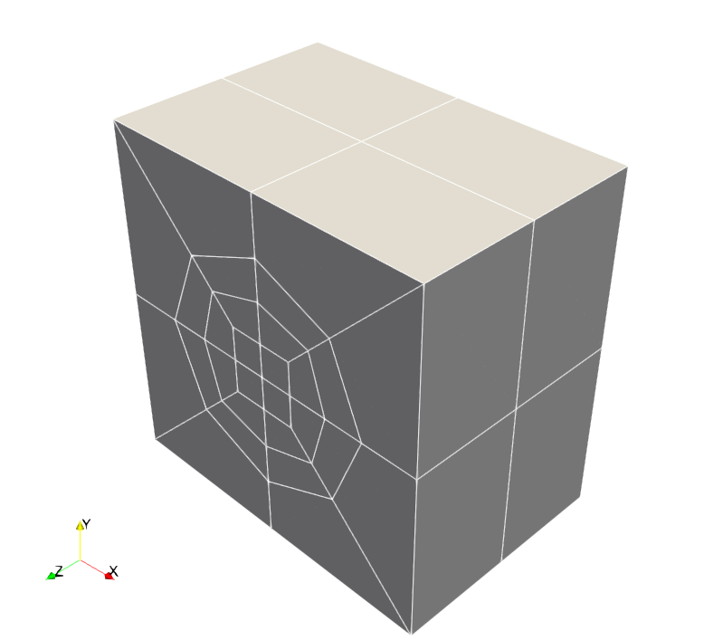
This three-dimensional mesh is a combination of an extruded square plate into a cube with a circular hole at the center and a cylinder that fits perfectly in the hole.
The following grid arguments can be prescribed:
R_cylinderis the radius of the cylinder mesh and of the hole in the extruded square plate;L_plateis the half of the edge length of the square;His the height in the z direction;n_subdivisionsis the number of subdivisions along the z direction.
The resulting cube will contain only the boundary ID 0 to identify its whole external boundary.
Upcoming update
A generalization to allow the prescription of different boundary conditions at each cube face will be done in the future.
Waveguide in a Cylindrical Cavity#
subsection mesh
  set type               = lethe
  set grid type          = pipe_and_waveguide
  set grid arguments     = 0.07 : 0.05 : 0.1 : 0.07 : 0.1 : 0.07 : 0.1 : 3 : 2 : 3 : true
end
This three-dimensional mesh is a waveguide embedded in a cylindrical cavity. The geometry consists of three sections joined along the z-axis: a bottom cylinder, a central cylinder into which the rectangular-based waveguide is embedded, and a top cylinder. The following grid arguments can be prescribed:
rectangle_widthis the waveguide width;rectangle_lengthis the waveguide length;outer_radiusis the radius of the main cylinder;inner_lengthdepends on the inner shape, since it can be the square side or the circle radius;bottom_heightis the height of the bottom cylinder;middle_heightis the height of the waveguide;top_heightis the height of the top cylinder;bottom_resolutionis the number of slices generated by the extrusion of the bottom cylinder
Warning
At least 2 slices are required in bottom_resolution.
middle_resolutionis the number of slices generated by the extrusion of the center cylinder;top_resolutionis the number of slices generated by the extrusion of the top cylinder;inner_circleindicates whether the inner shape is a circle (true) or a square (false). Default istrue.
Boundary IDs are assigned as follows:
0: Microwaves (MW) inlet1: Fluid flow inlet (bottom surface of the cylinder)2: Fluid flow outlet (top surface of the cylinder)3: Walls
Material IDs are assigned as follows:
0: Fluid in the channel (cylinder)1: Air in the waveguide (paving stone)
A CylindricalManifold is attached to the curved lateral surfaces of the cylinder so that mesh refinement preserves the shape of the fluid channel.