Rectangular Hopper#
This example simulates the filling and discharging of particles in a rectangular hopper. We set up this simulation based on the simulation of Anand et al. [1] It is recommended to visit DEM parameters for more detailed information on the concepts and physical meanings of the parameters in Lethe-DEM. The main example does not use periodic boundary conditions in the depth of the hopper like article, but an extended case, presented at the end, does.
Features#
Solvers:
lethe-particlesFloating walls
GMSH grids
Python post-processing script using PyVista
Periodic boundaries in DEM (see section Case with Periodic Boundary Conditions)
Files Used in This Example#
Parameter file:
examples/dem/3d-rectangular-hopper/hopper.prm
Description of the Case#
This simulation consists of two stages: filling (0-4 s) and discharge (4-7.5 s) of particles. Anand et al. uses periodic boundaries in the z axis allowing to use a thin width for simulation. In the main example, we do not consider periodic boundaries. To minimize the impact of collision of particle with walls along the z axis, the width and the number of particle were multiplied by 6 (40740 particles instead of 6790). This corresponds to a width of 15 times the particle diameter.
Parameter File#
Mesh#
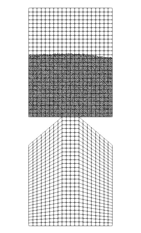
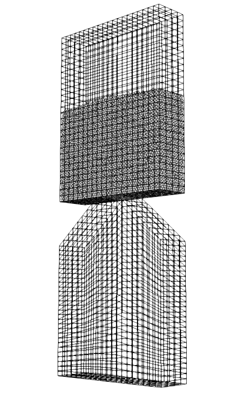
The mesh is a hopper with 90° angle generated with GMSH having a top part for the filling and a bottom part which acts as a collector of the particle. The geometry follow the Anand et al. [1] base case and was handled in order to generate a structured mesh.
subsection mesh
  set type                                = gmsh
  set file name                           = hopper_structured.msh
  set initial refinement                  = 1
  set expand particle-wall contact search = false
  set check diamond cells                 = true
end
Insertion Info#
An insertion box is defined inside and the top part of the hopper. The inserted number of particles per time step is chosen to be a factor of the total number of particle. In this case, 14 insertion steps are required to fill up the hopper with particles.
subsection insertion info
  set insertion method                               = volume
  set inserted number of particles at each time step = 2910
  set insertion frequency                            = 25000
  set insertion box points coordinates               = -0.06, 0.10644, .00224 : 0.06, 0.16020, 0.03136
  set insertion distance threshold                   = 1.5
  set insertion maximum offset                       = 0.1
  set insertion prn seed                             = 20
end
Lagrangian Physical Properties#
The total number of particles in this simulation is 40740. All particles have a diameter of 2.24 mm.
The following properties are chosen according to the Anand et al. paper :
Uniform distribution of spherical particles
Diameter (2.24 mm)
Density of glass (2.5 g/cm³)
Restitution coefficient of particle-particle (0.94)
Restitution coefficient of particle-wall (0.90)
Friction coefficient of particle-particle (0.2)
subsection lagrangian physical properties
  set g                        = 0.0, -9.81, 0.0
  set number of particle types = 1
  subsection particle type 0
    set size distribution type            = uniform
    set diameter                          = 0.00224
    set number of particles               = 40740
    set density particles                 = 2500
    set young modulus particles           = 1e6
    set poisson ratio particles           = 0.3
    set restitution coefficient particles = 0.94
    set friction coefficient particles    = 0.2
    set rolling friction particles        = 0.1786
  end
  set young modulus wall           = 1e6
  set poisson ratio wall           = 0.3
  set friction coefficient wall    = 0.2
  set restitution coefficient wall = 0.9
  set rolling friction wall        = 0.1786
end
Model Parameters#
Model parameters are based on the Silo example.
subsection model parameters
  subsection contact detection
    set contact detection method                = dynamic
    set dynamic contact search size coefficient = 0.9
    set neighborhood threshold                  = 1.3
  end
  subsection load balacing
    set load balance method                     = frequent
    set frequency                               = 50000
  end
  set particle particle contact force method    = hertz_mindlin_limit_overlap
  set particle wall contact force method        = nonlinear
  set rolling resistance torque method          = constant
  set integration method                        = velocity_verlet
end
Simulation Control#
The time end of the simulation is 7.5 where most of the particles are discharged and the DEM time step is 1e-5 s which corresponds to 2.9% of Rayleigh time step.
subsection simulation control
  set time step        = 1e-5
  set time end         = 7.5
  set log frequency    = 1000
  set output frequency = 1000
  set output path      = ./output/
  set output name      = hopper
  set output boundaries = true
end
Floating Walls#
Floating wall in this example is handled as explained in the Silo example.
subsection floating walls
  set number of floating walls = 1
  subsection wall 0
    set point on wall = 0., 0., 0.
    set normal vector = 0., 1., 0.
    set start time = 0
    set end time   = 4
  end
end
Running the Simulation#
To launch the simulation, the mesh must first be generated. Assuming that GMSH is installed on your machine, the following command can be used:
This simulation can be launched by
.
Post-processing#
A Python post-processing code called hopper_post_processing.py is provided with this example. It is used to measure the flow rate of particles.
It also compares the data generated by the simulation to data from Anand et al. [1]
It is possible to run the post-processing code with the following line. The arguments are the simulation path and the prm file name.
Important
You need to ensure that lethe_pyvista_tools is working on your machine. Click here for details.
Results Post-processing#
Mass flow rate results after post-processing and comparison with the results of Anand et al. [1] for the base case of the hooper with a 90° angle.
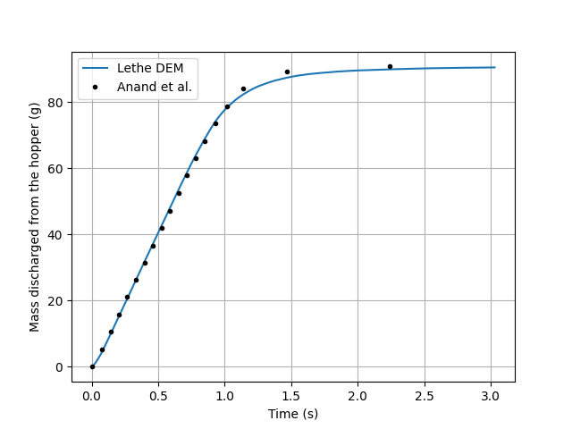
Mass discharge results.#
Results#
As seen in the following figure, the simulation was not run until all the particles are discharged in the bottom part. Since the mass flow rate is constant during the discharge, simulating the very end is not necessary. The simulated mass discharging rate is 82.79 g/s.
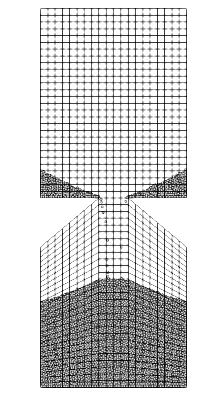
Rectangular hopper at the end of the simulation.#
Case with Periodic Boundary Conditions#
Periodic boundary conditions feature was not implemented when this example was created. Since it is now, this example is now extended to show how to use it. The original case in Anand et al. [1] did use periodic boundaries. The modifications on the parameters of the previous example is the mesh thickness and the number of particles and also the addition of the boundary condition section.
Mesh#
The hopper in this case has the same shape with a depth reduces by a factor of 6. The depth is the same than the article and a new GMSH file is used.
subsection mesh
    set type                                = gmsh
    set file name                           = hopper_structured_periodic.msh
    set initial refinement                  = 1
    set expand particle-wall contact search = false
    set check diamond cells                 = true
end
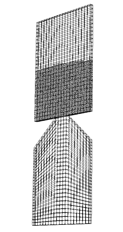
Rectangular periodic hopper packed with particle before the discharge with a 3d view.#
Boundary Conditions#
The previous example did not need any parameters on a section for the boundary conditions since all walls are treated as solid boundaries by default. We need to specify which boundaries are periodic and the perpendicular direction, here the periodic ids are 0 and 1 and the axis is z, corresponding to value of 2. The feature only works with one pair of periodic boundaries.
subsection DEM boundary conditions
    set number of boundary conditions = 1

    subsection boundary condition 0
        set type                      = periodic
        set periodic id 0             = 1
        set periodic id 1             = 2
        set periodic direction        = 2
    end
end
Lagrangian Physical Properties#
The total number of particles of this simulation is 6790: 6 times less than the previous example.
subsection lagrangian physical properties
    set g                        = 0.0, -9.81, 0.0
    set number of particle types = 1
    subsection particle type 0
        set size distribution type            = uniform
        set diameter                          = 0.00224
        set number                            = 6790
        set density particles                 = 2500
        set young modulus particles           = 1e6
        set poisson ratio particles           = 0.3
        set restitution coefficient particles = 0.94
        set friction coefficient particles    = 0.2
        set rolling friction particles        = 0.1786
    end
    set young modulus wall           = 1e6
    set poisson ratio wall           = 0.3
    set friction coefficient wall    = 0.2
    set restitution coefficient wall = 0.9
    set rolling friction wall        = 0.1786
end
Insertion Info#
Since the geometry of the mesh and the number of the particles are not the same, the insertion info have to be modified according to the new domain of the mesh with an inserted number of particles corresponding to the new number.
subsection insertion info
    set insertion method                               = volume
    set inserted number of particles at each time step = 485
    set insertion frequency                            = 25000
    set insertion box points coordinates               = -0.06, 0.10644, .00112 : 0.06, 0.16020, 0.00448
    set insertion distance threshold                   = 1.5
    set insertion maximum offset                       = 0.1
    set insertion prn seed                             = 20
end
Running the Simulation#
Similarly to the non-periodic rectangular hopper simulation, the mesh must first be generated using the following command
, and launched by
.
Results Comparison#
Here is the comparison of the results between the original simulation with Lethe, the periodic boundary conditions simulation with Lethe and the results from Anand et al.. paper. The simulated mass discharging rate is 82.79 g/s from the original simulation and 87.43 g/s from the one with PBC which is in better agreement with Anand et al. results. The run time of the simulation goes from about 26 minutes to 1 minute 42 seconds when using PBC on 16 cores with an AMD Ryzen 7950X processor.
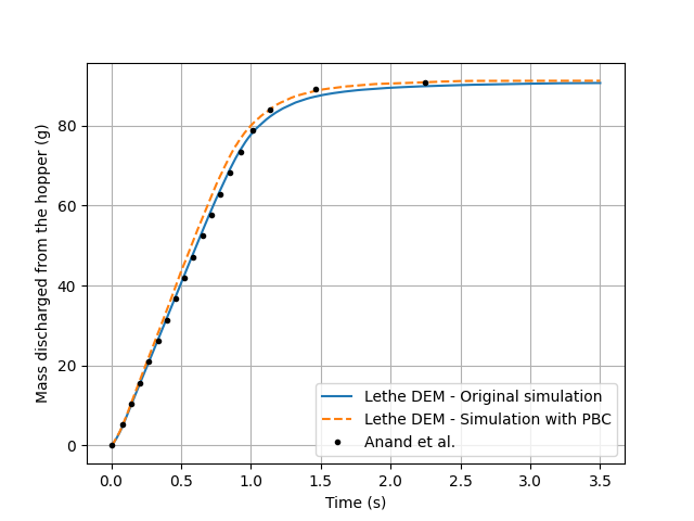
Comparison of mass discharge results from the 2 simulations and the journal article.#
