Simple Plane Model From Composite#
This example aims to showcase the vast possibilities of objects that can be defined using the composite shape in the sharp immersed boundary solver. It also aims to give an example of the type of operations that can be made on these geometries.
Features#
Solvers:
lethe-fluid-sharpGeometry definition
Files Used in this Example#
Both files mentioned below are located in the example’s folder (examples/sharp-immersed-boundary/simple-plane-model-from-composite).
Composite geometry file:
plane.compositeParameter file:
plane.prm
Description of the Case#
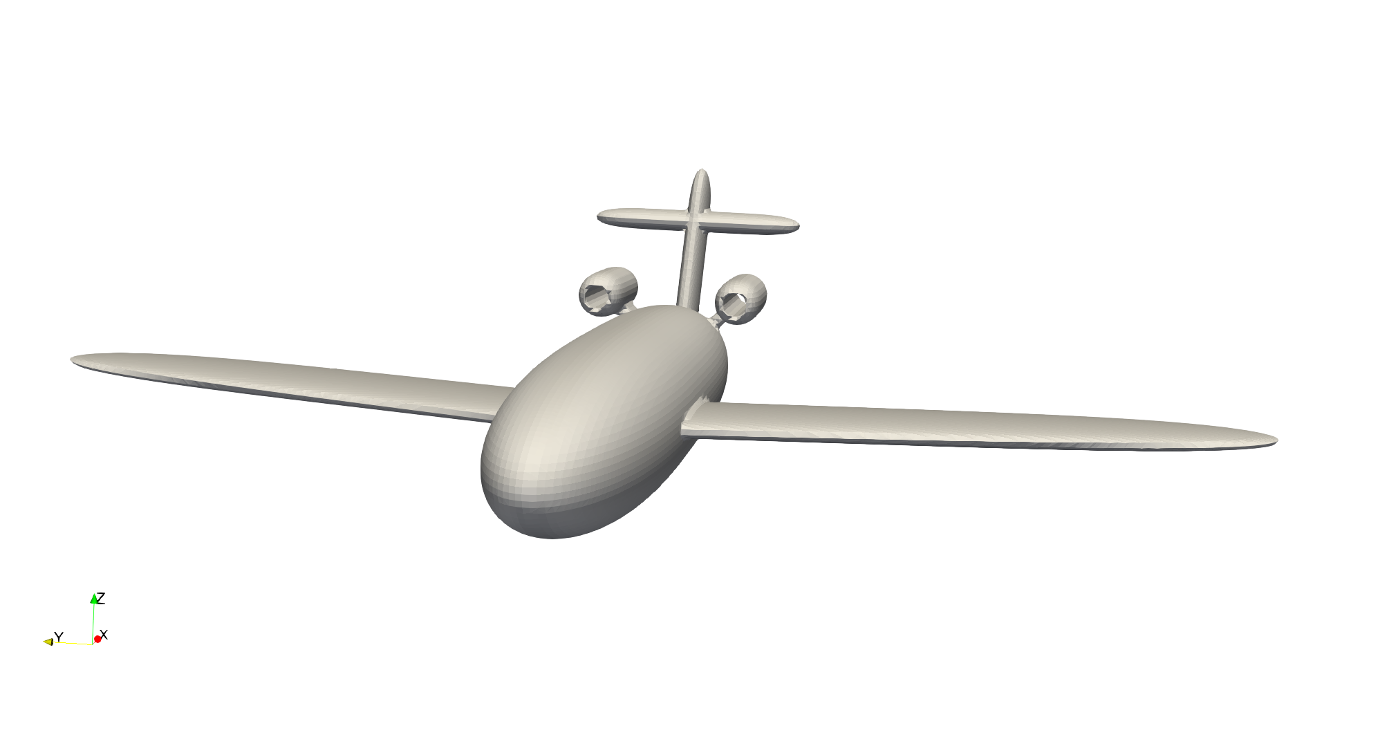
This example presents the creation of a simple plane model using a composite shape. This example does a step-by-step creation of the shape. This plane is not a real model. The parameters used only aim at showcasing the different operations of the composite shape creation. The final product will look as follows:
Creation of the Composite Shape File#
The shape is created in two steps inspired by the GMSH syntax.
Basic shape definitions. Shapes are defined with different parameters: shape ID, shape type, arguments, position, and orientation.
Boolean operations definitions. Operations are defined by: operation ID, operation type, shape 1 ID, shape 2 ID.
Shapes and boolean operations each have an ID, and boolean operations can reference previous operations to build upon them. The final shape obtained is the product of the operation with the largest ID. To facilitate shape creation, we start indexing the operations from ID 30. This index is much larger than the number of primitives used.
All the shapes are placed in the reference frame of the composite shape which can then be moved depending on the position and orientation of the shape prescribed in the parameter file of the case. Here, we only focus on the step-by-step operation required to generate this complex shape.
Note
This model uses multiple shapes that are referred to as superquadric ellipsoids. This superquadric shape has at least two axes defined using a 2-order power. Any slice of this type of superquadric, parallel to the plane defined by these two axes, is an ellipse. If the remaining axis has a higher power, then the shape will tend toward an extrusion of an ellipse with a rounded tip.
The plane.composite file contains these instructions. The plane along the X-axis and the positive Z-axis is in the above direction of the plane. The Y-axis points in the left direction of the plane.
Warning
The human interpretation of the composite files is cumbersome. For this reason we add comments to each line.
shapes
0;    superquadric;   0.3:2.5:0.05:2:6:2;           0.1:0:0 ;      0:-0.05:0.25 # Full left wing
1; hyper rectangle;                5:5:5;            0:-5:0 ;             0:0:0 # Cube to trim off the right side of the left wing
2;    superquadric;   0.3:2.5:0.05:2:6:2;           0.1:0:0 ;     0:-0.05:-0.25 # Full right wing
3; hyper rectangle;                5:5:5;             0:5:0 ;             0:0:0 # Cube to trim off the left side of the right wing
4;    superquadric;    1.5:0.3:0.3:3:2:2;         -0.25:0:0 ;             0:0:0 # Fuselage of the plane
5;    superquadric;  0.15:0.05:0.5:2:2:6;       -1.75:0:0.4 ;          0:-0.5:0 # Tail wing vertical plan
6;    superquadric;  0.15:0.5:0.05:2:6:2;       -1.85:0:0.6 ;             0:0:0 # Tail wing horizontal plan
7;    superquadric;    0.3:0.1:0.1:5:2:2;     -1.25:0.3:0.3 ;             0:0:0 # Left engine shape
8;        cylinder;               0.05:1;     -1.25:0.3:0.3 ; 0:1.57079632679:0 # Left engine hole
9;    superquadric;    0.3:0.1:0.1:5:2:2;    -1.25:-0.3:0.3 ;             0:0:0 # Right engine shape
10;       cylinder;               0.05:1;    -1.25:-0.3:0.3 ; 0:1.57079632679:0 # Right engine hole
11;   superquadric;  0.1:0.03:0.25:6:2:2;   -1.25:0.15:0.15 ;   -0.78539816:0:0 # Left engine link
12;   superquadric;  0.1:0.03:0.25:6:2:2;  -1.25:-0.15:0.15 ;    0.78539816:0:0 # Right engine link
operations
30; difference  ; 1:0   # Trim off the left wing
31; difference  ; 3:2   # Trim off the right wing
32; union       ; 30:31 # Combine the two wings
33; union       ; 32:4  # Combine the wings with the plane fuselage
34; union       ; 33:5  # Combine vertical part of the tail wing with the fuselage
35; union       ; 34:6  # Combine horizontal part of the tail wing with the fuselage
36; difference  ; 8:7   # Hole in the left engine
37; union       ; 35:36 # Combine left engine with the fuselage
38; difference  ; 10:9  # Hole in the right engine
39; union       ; 37:38 # Combine right engine with the fuselage and the other engine
40; difference  ; 7:11  # Trim off  the left engine link with the engine shape
41; difference  ; 9:12  # Trim off the right engine link with the engine shape
42; union       ; 39:40 # Combine the left engine link with the rest of the plane
43; union       ; 42:41 # Combine the right engine link with the rest of the plane
Let us read this file step-by-step line-by-line:
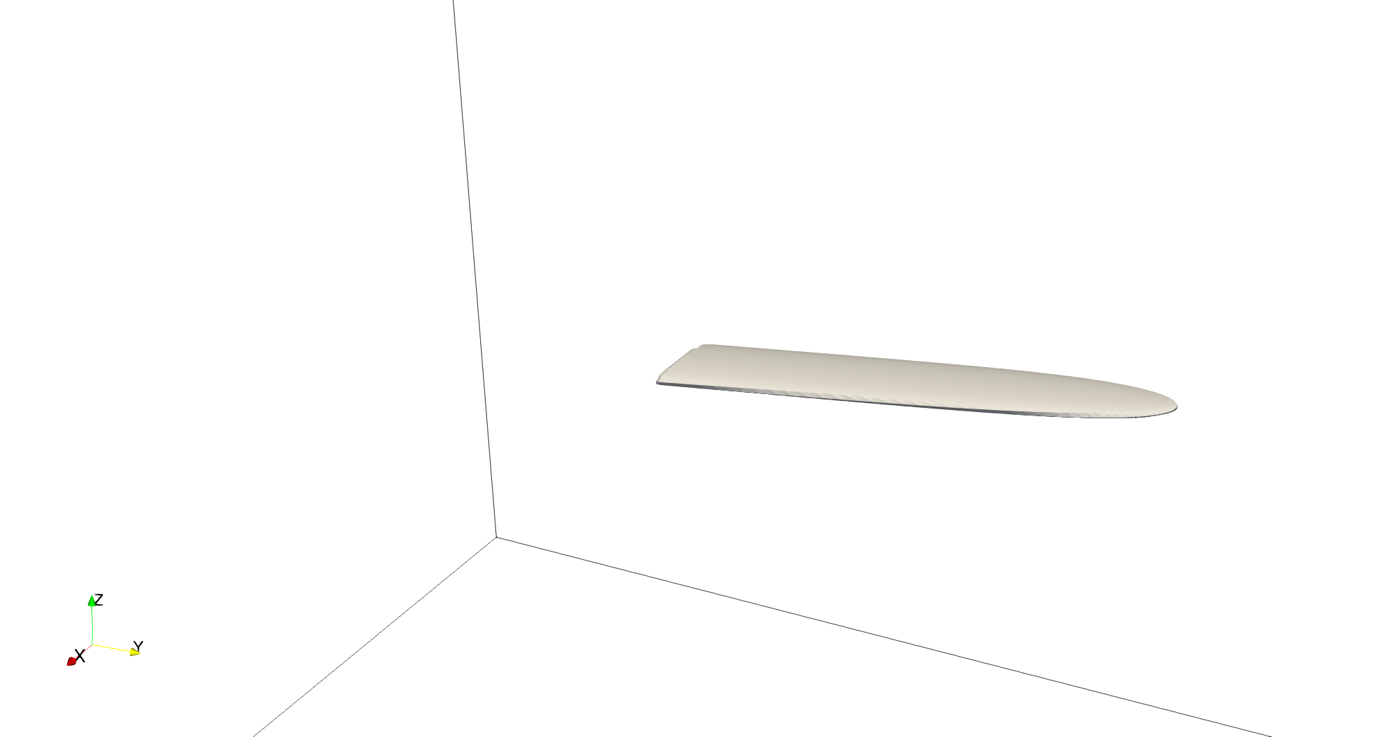
First, we create the left wing. This wing is created using a superquadric ellipsoid shape. Along the cord, we use an elongated ellipsoid with length 0.6 and 0.1 thickness. In the wingspan direction, the wing is defined by a 6-order power superquadric with a half wingspan of 2.5. We then tilt the wing backward by 0.25 rad and give a small angle of attack of 0.05 rad. Since the wing is now tilted backward, the right side of the superquadric shape is undesirable, so we remove it using a hypercube to trim the right side of the wing.
shapes
0;    superquadric;   0.3:2.5:0.05:2:6:2;           0.1:0:0 ;      0:-0.05:0.25 # Full left wing
1; hyper rectangle;                5:5:5;            0:-5:0 ;             0:0:0 # Cube to trim off the right side of the left wing
operations
30; difference  ; 1:0   # Trim off the left wing
This step gives us the first wing of the plane.
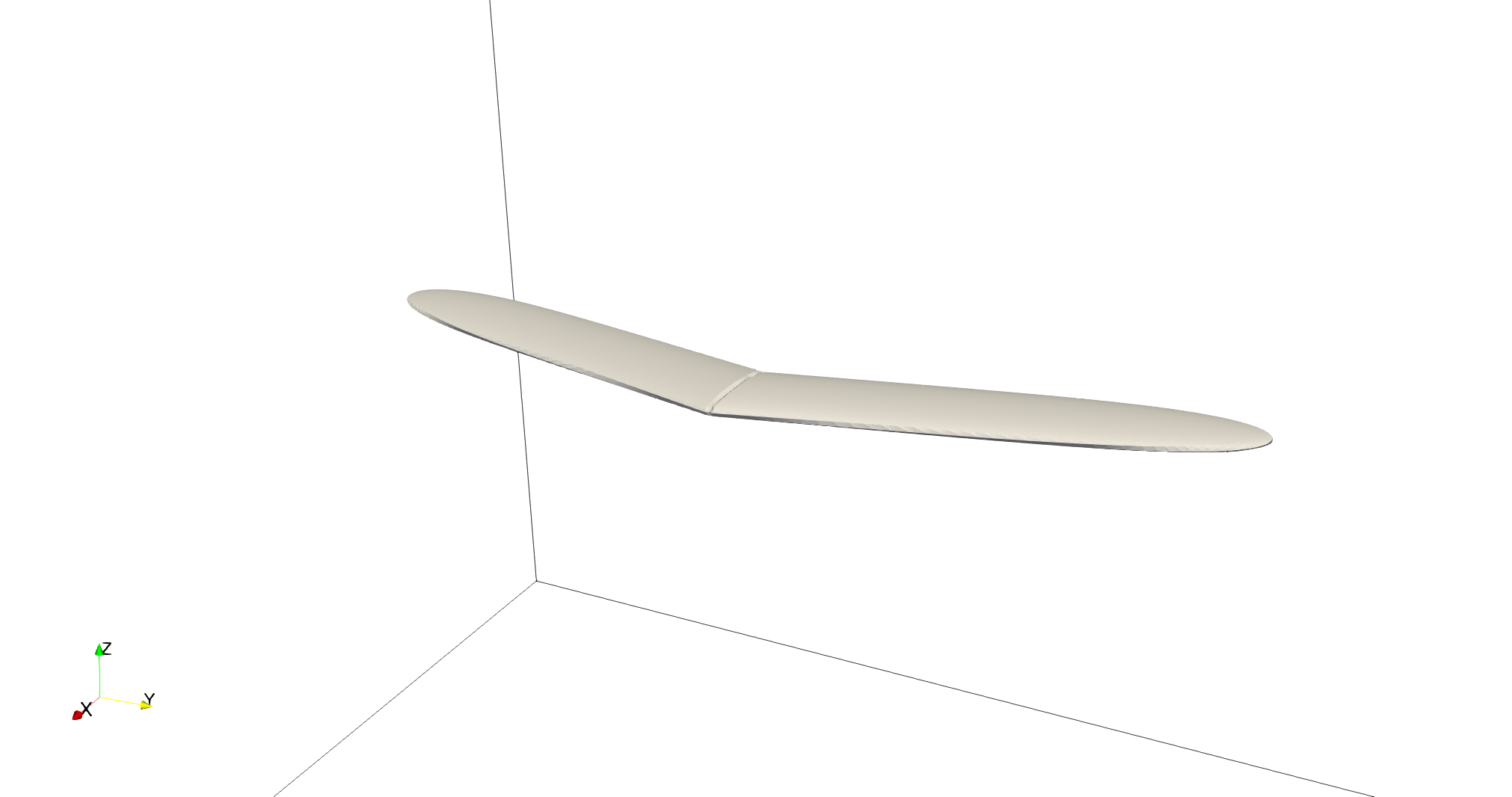
We repeat the same operation for the right wing and add a union of the left and right wing.
shapes
0;    superquadric;   0.3:2.5:0.05:2:6:2;           0.1:0:0 ;      0:-0.05:0.25 # Full left wing
1; hyper rectangle;                5:5:5;            0:-5:0 ;             0:0:0 # Cube to trim off the right side of the left wing
2;    superquadric;   0.3:2.5:0.05:2:6:2;           0.1:0:0 ;     0:-0.05:-0.25 # Full right wing
3; hyper rectangle;                5:5:5;             0:5:0 ;             0:0:0 # Cube to trim off the left side of the right wing
operations
30; difference  ; 1:0   # Trim off the left wing
31; difference  ; 3:2   # Trim off the right wing
32; union       ; 30:31 # Combine the two wings
This step gives us the first wing of the plane.
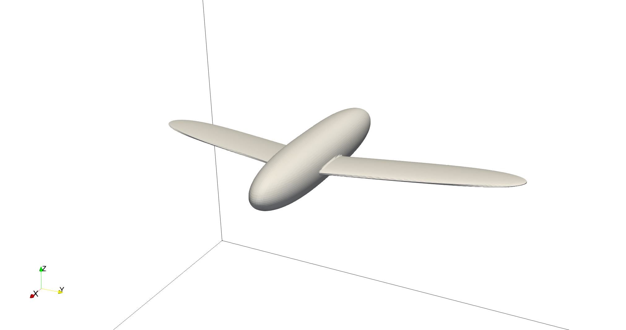
Next, we add the fuselage of the plane. We approximate the fuselage with a circular superquadric shape with a length of 3 and a radius of 0.3. On the length of the plane, the superquadric is of power 3. We want the wings to be a bit more at the front of the fuselage, so we move the fuselage slightly backward by 0.25. We then add the combination of the wings and the fuselage.
shapes
0;    superquadric;   0.3:2.5:0.05:2:6:2;           0.1:0:0 ;      0:-0.05:0.25 # Full left wing
1; hyper rectangle;                5:5:5;            0:-5:0 ;             0:0:0 # Cube to trim off the right side of the left wing
2;    superquadric;   0.3:2.5:0.05:2:6:2;           0.1:0:0 ;     0:-0.05:-0.25 # Full right wing
3; hyper rectangle;                5:5:5;             0:5:0 ;             0:0:0 # Cube to trim off the left side of the right wing
4;    superquadric;    1.5:0.3:0.3:3:2:2;         -0.25:0:0 ;             0:0:0 # Fuselage of the plane
operations
30; difference  ; 1:0   # Trim off the left wing
31; difference  ; 3:2   # Trim off the right wing
32; union       ; 30:31 # Combine the two wings
33; union       ; 32:4  # Combine the wings with the plane fuselage
This step gives us the following wings and fuselage of the plane.
We continue with the addition of the tail wing. The tail wing is made from a combination of two superquadric ellipsoid shapes, one for the vertical plane of the tail wing and one for the horizontal plane of the tail wing. Along the cord of these sections, the shapes are made from elongated ellipsoids with a minor axis of 0.1 and a main axis of 0.3. The span of both shapes is defined using a 6-order power of length 1. The position is adjusted to fit with the tail of the fuselage.
shapes
0;    superquadric;   0.3:2.5:0.05:2:6:2;           0.1:0:0 ;      0:-0.05:0.25 # Full left wing
1; hyper rectangle;                5:5:5;            0:-5:0 ;             0:0:0 # Cube to trim off the right side of the left wing
2;    superquadric;   0.3:2.5:0.05:2:6:2;           0.1:0:0 ;     0:-0.05:-0.25 # Full right wing
3; hyper rectangle;                5:5:5;             0:5:0 ;             0:0:0 # Cube to trim off the left side of the right wing
4;    superquadric;    1.5:0.3:0.3:3:2:2;         -0.25:0:0 ;             0:0:0 # Fuselage of the plane
5;    superquadric;  0.15:0.05:0.5:2:2:6;       -1.75:0:0.4 ;          0:-0.5:0 # Tail wing vertical plan
6;    superquadric;  0.15:0.5:0.05:2:6:2;       -1.85:0:0.6 ;             0:0:0 # Tail wing horizontal plan
operations
30; difference  ; 1:0   # Trim off the left wing
31; difference  ; 3:2   # Trim off the right wing
32; union       ; 30:31 # Combine the two wings
33; union       ; 32:4  # Combine the wings with the plane fuselage
34; union       ; 33:5  # Combine vertical part of the tail wing with the fuselage
35; union       ; 34:6  # Combine horizontal part of the tail wing with the fuselage
This step gives us the following plane without engines.
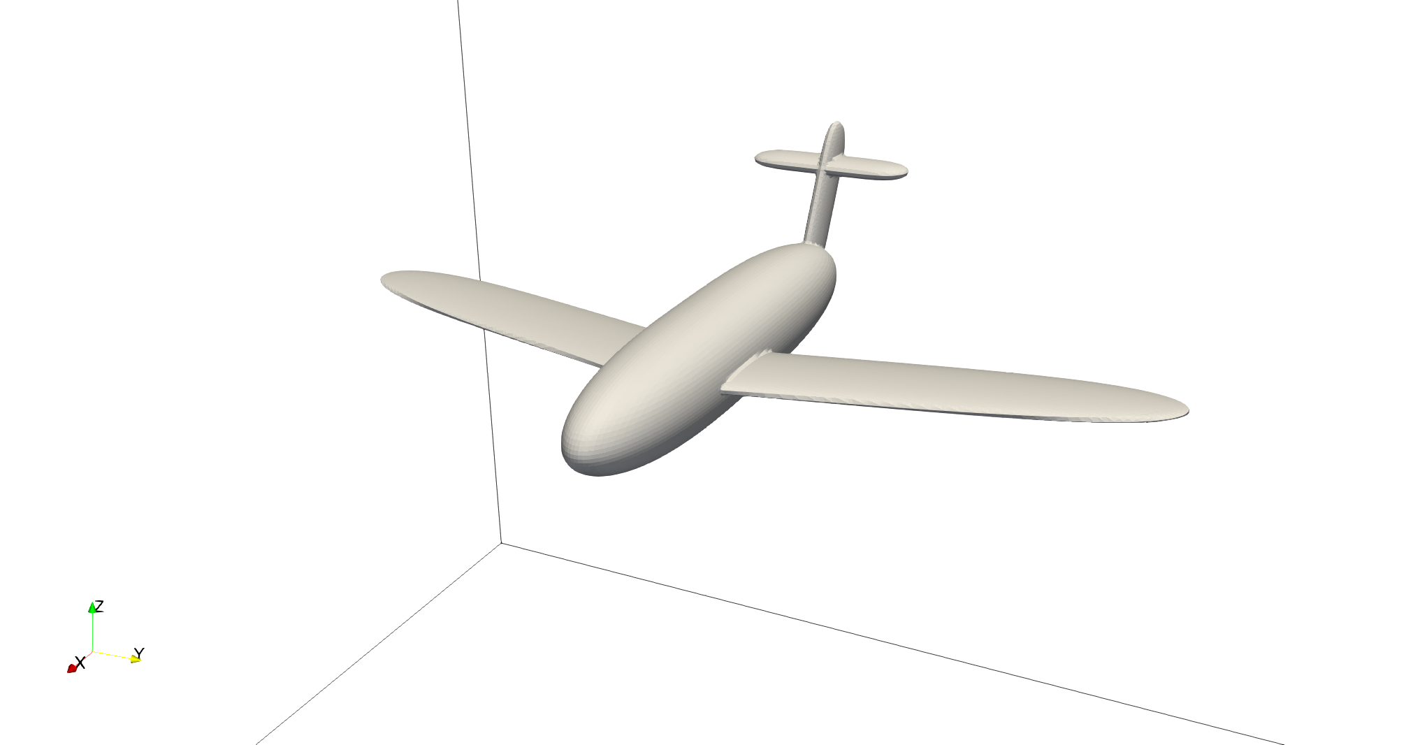
The next step is the addition of the two engines. To keep the model relatively simple, the engines are defined by a simple circular superquadric shape with a hole at the center. The radius of the engine is 0.1, and the length is 0.6. The superquadric power used for the superquadric axis is 5. The engine’s position is adjusted to fit the plane model, with a 45-degree angle with the center of the fuselage. The hole inside the superquadric shape is obtained using a long cylinder of radius 0.05 centered on the same axis.
shapes
0;    superquadric;   0.3:2.5:0.05:2:6:2;           0.1:0:0 ;      0:-0.05:0.25 # Full left wing
1; hyper rectangle;                5:5:5;            0:-5:0 ;             0:0:0 # Cube to trim off the right side of the left wing
2;    superquadric;   0.3:2.5:0.05:2:6:2;           0.1:0:0 ;     0:-0.05:-0.25 # Full right wing
3; hyper rectangle;                5:5:5;             0:5:0 ;             0:0:0 # Cube to trim off the left side of the right wing
4;    superquadric;    1.5:0.3:0.3:3:2:2;         -0.25:0:0 ;             0:0:0 # Fuselage of the plane
5;    superquadric;  0.15:0.05:0.5:2:2:6;       -1.75:0:0.4 ;          0:-0.5:0 # Tail wing vertical plan
6;    superquadric;  0.15:0.5:0.05:2:6:2;       -1.85:0:0.6 ;             0:0:0 # Tail wing horizontal plan
7;    superquadric;    0.3:0.1:0.1:5:2:2;     -1.25:0.3:0.3 ;             0:0:0 # Left engine shape
8;        cylinder;               0.05:1;     -1.25:0.3:0.3 ; 0:1.57079632679:0 # Left engine hole
9;    superquadric;    0.3:0.1:0.1:5:2:2;    -1.25:-0.3:0.3 ;             0:0:0 # Right engine shape
10;       cylinder;               0.05:1;    -1.25:-0.3:0.3 ; 0:1.57079632679:0 # Right engine hole
operations
30; difference  ; 1:0   # Trim off the left wing
31; difference  ; 3:2   # Trim off the right wing
32; union       ; 30:31 # Combine the two wings
33; union       ; 32:4  # Combine the wings with the plane fuselage
34; union       ; 33:5  # Combine vertical part of the tail wing with the fuselage
35; union       ; 34:6  # Combine horizontal part of the tail wing with the fuselage
36; difference  ; 8:7   # Hole in the left engine
37; union       ; 35:36 # Combine left engine with the fuselage
38; difference  ; 10:9  # Hole in the right engine
39; union       ; 37:38 # Combine right engine with the fuselage and the other engine
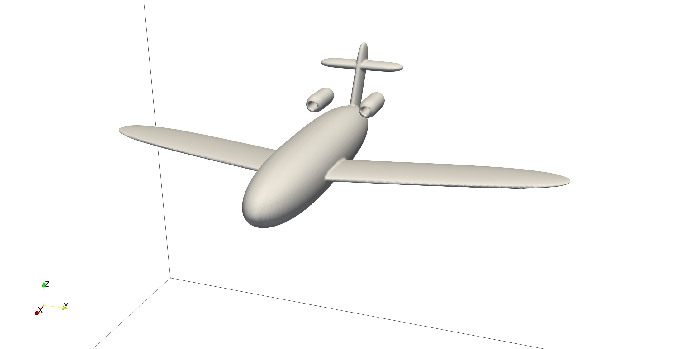
The final step is to add a link between the engine model and the fuselage of the plane. This is done using another superquadric ellipsoid shape. The ellipse main axis has a length of 0.06, and the minor axis has a length of 0.06. The superquadric axis is of length 0.5. To avoid blocking the hole of the engine with this link to the fuselage, we use the superquadric shape that defines the shape of the engine to trim this superquadric shape. The resulting shape is then combined with the rest of the fuselage. The position is adjusted to fit well with the engine’s position.
shapes
0;    superquadric;   0.3:2.5:0.05:2:6:2;           0.1:0:0 ;      0:-0.05:0.25 # Full left wing
1; hyper rectangle;                5:5:5;            0:-5:0 ;             0:0:0 # Cube to trim off the right side of the left wing
2;    superquadric;   0.3:2.5:0.05:2:6:2;           0.1:0:0 ;     0:-0.05:-0.25 # Full right wing
3; hyper rectangle;                5:5:5;             0:5:0 ;             0:0:0 # Cube to trim off the left side of the right wing
4;    superquadric;    1.5:0.3:0.3:3:2:2;         -0.25:0:0 ;             0:0:0 # Fuselage of the plane
5;    superquadric;  0.15:0.05:0.5:2:2:6;       -1.75:0:0.4 ;          0:-0.5:0 # Tail wing vertical plan
6;    superquadric;  0.15:0.5:0.05:2:6:2;       -1.85:0:0.6 ;             0:0:0 # Tail wing horizontal plan
7;    superquadric;    0.3:0.1:0.1:5:2:2;     -1.25:0.3:0.3 ;             0:0:0 # Left engine shape
8;        cylinder;               0.05:1;     -1.25:0.3:0.3 ; 0:1.57079632679:0 # Left engine hole
9;    superquadric;    0.3:0.1:0.1:5:2:2;    -1.25:-0.3:0.3 ;             0:0:0 # Right engine shape
10;       cylinder;               0.05:1;    -1.25:-0.3:0.3 ; 0:1.57079632679:0 # Right engine hole
11;   superquadric;  0.1:0.03:0.25:6:2:2;   -1.25:0.15:0.15 ;   -0.78539816:0:0 # Left engine link
12;   superquadric;  0.1:0.03:0.25:6:2:2;  -1.25:-0.15:0.15 ;    0.78539816:0:0 # Right engine link
operations
30; difference  ; 1:0   # Trim off the left wing
31; difference  ; 3:2   # Trim off the right wing
32; union       ; 30:31 # Combine the two wings
33; union       ; 32:4  # Combine the wings with the plane fuselage
34; union       ; 33:5  # Combine vertical part of the tail wing with the fuselage
35; union       ; 34:6  # Combine horizontal part of the tail wing with the fuselage
36; difference  ; 8:7   # Hole in the left engine
37; union       ; 35:36 # Combine left engine with the fuselage
38; difference  ; 10:9  # Hole in the right engine
39; union       ; 37:38 # Combine right engine with the fuselage and the other engine
40; difference  ; 7:11  # Trim off  the left engine link with the engine shape
41; difference  ; 9:12  # Trim off the right engine link with the engine shape
42; union       ; 39:40 # Combine the left engine link with the rest of the plane
43; union       ; 42:41 # Combine the right engine link with the rest of the plane
This final step gives us the full plane model.

Parameter File#
The parameter file for this case simply produces an output to visualize the shape created by this composite file. We recall that to visualize the shape you must use the contour function of your post-processing tool on the level field and plot the contour of levelset=0
# Listing of Parameters
#----------------------

set dimension = 3

#---------------------------------------------------
# Simulation Control
#---------------------------------------------------

subsection simulation control
  set method            = steady
  set output name       = composite_shape_build
  set output frequency  = 1
end

#---------------------------------------------------
# Mesh
#---------------------------------------------------

subsection mesh
  set type               = dealii
  set grid type          = subdivided_hyper_rectangle
  set grid arguments     = 1,1,1:-5,-5,-5 : 5 , 5 , 5 : true
  set initial refinement = 4
end


#---------------------------------------------------
# Timer
#---------------------------------------------------

subsection timer
  set type = iteration
end

#---------------------------------------------------
# Mesh Adaptation Control
#---------------------------------------------------

subsection mesh adaptation
  set type                 = kelly
  set fraction type        = number
end

#---------------------------------------------------
# IB particles
#---------------------------------------------------

subsection particles
  set number of particles                     = 1
  set assemble Navier-Stokes inside particles = false

  subsection local mesh refinement
    set initial refinement                = 5
    set refine mesh inside radius factor  = 1
    set refine mesh outside radius factor = 1
  end

  subsection particle info 0
    subsection position
      set Function expression = 0;0;0
    end
    subsection orientation
      set Function expression = 0;0;0
    end
    set type            = composite
    set shape arguments = plane.composite
  end
end