Gas-Solid Spouted Cylinder Bed#
This example is an extension of the Gas-Solid Spouted Bed for a cylindrical geometry.
Features#
Solvers:
lethe-particlesandlethe-fluid-particlesThree-dimensional problem
Simulates a solid-gas cylinder-shaped spouted bed
Files Used in this Example#
Both files mentioned below are located in the example’s folder (examples/unresolved-cfd-dem/gas-solid-spouted-cylinder-bed).
Parameter file for particle generation and packing:
packing-particles.prmParameter file for CFD-DEM simulation of the spouted bed:
gas-solid-spouted-cylinder-bed.prm
Description of the Case#
This example simulates the spouting of spherical particles in a cylinder. As noted in the example of Gas-Solid Spouted Bed, we use lethe-particles to fill the bed with particles, and lethe-fluid-particles as the unresolved CFD-DEM solver.
DEM Parameter File#
Here, we will focus only on the parts that have been modified compared to the Gas-Solid Spouted Bed example. It is also strongly recommended to visit the DEM parameters for a detailed description on the concepts and physical meanings of the DEM parameters.
Mesh#
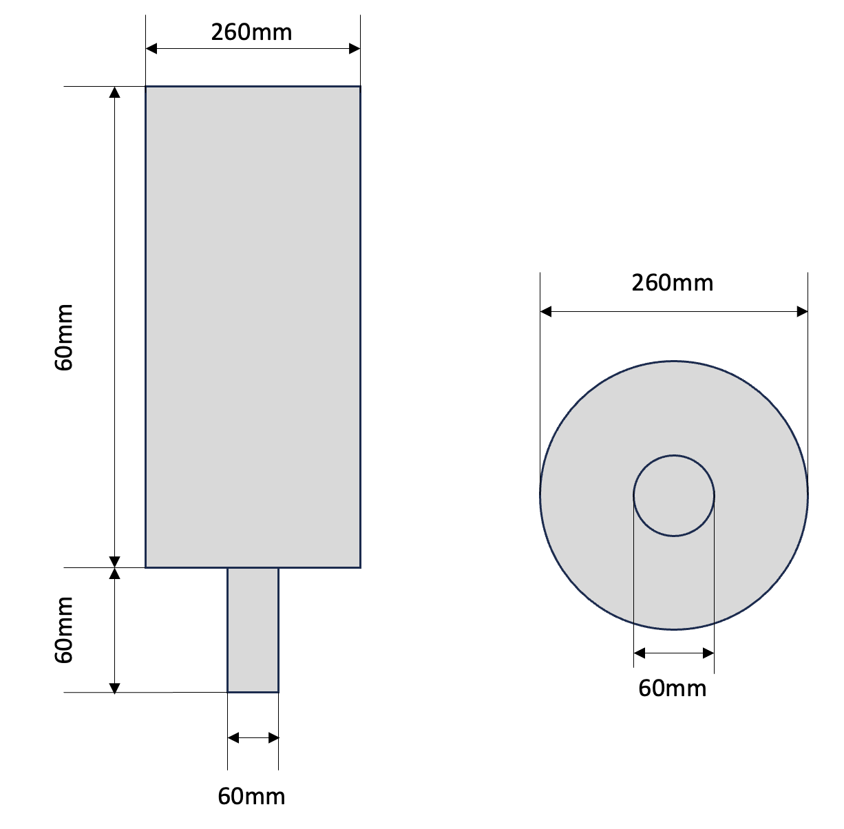
In this example, we are simulating a cylinder shaped spouted bed. We introduce the flow through a cylinder of smaller radius that constitutes the inlet of the bed. A schematic image is shown below;

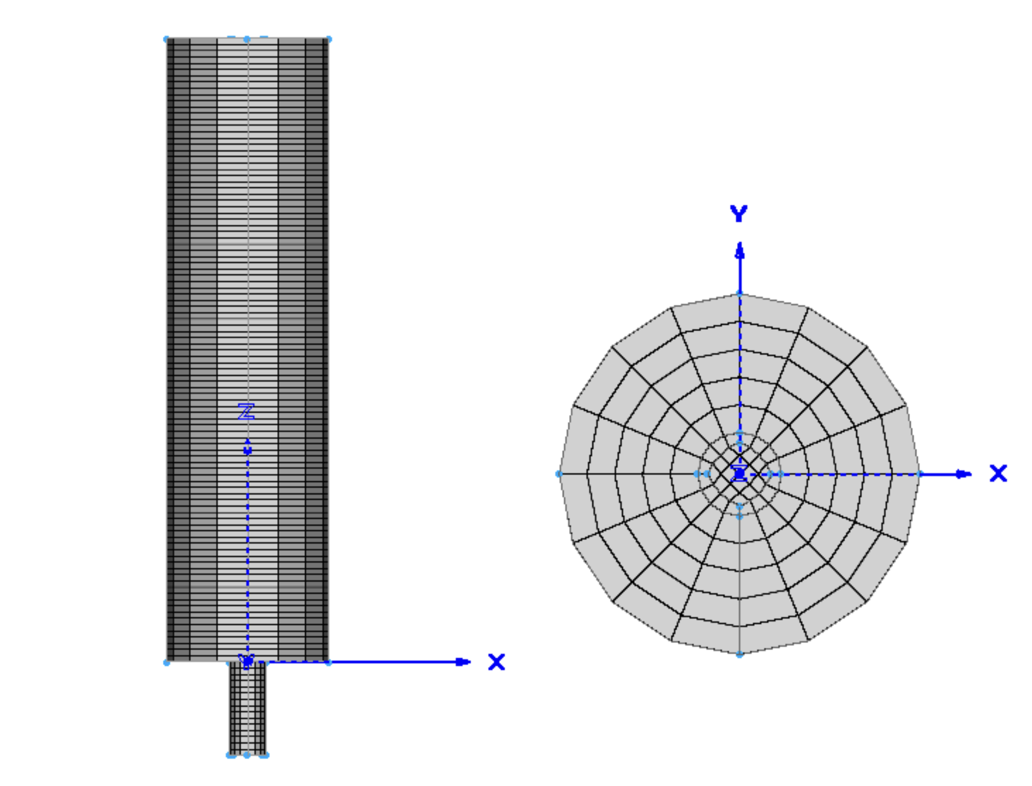
The geometry of the bed was created using Pointwise. An overview of the mesh is:

In unresolved CFD-DEM, the averaging volume used to calculate the void fraction needs to be large enough to contain several particles (>10). Since the averaging volume used in the quadrature-centred method is generally related to the cell volume, this introduces a limitation on the cell size. In general, the averaging volume, which in this case is controlled by the cell size, should be approximately three times larger than the diameter of the particles in order to get stable calculation.
subsection mesh
  set type                                = gmsh
  set file name                           = ./mesh/cylinder-spouted-bed.msh
  set expand particle-wall contact search = true
end
where the file name includes the path to the mesh file. Here, we activate expand particle-wall contact search, which is only used in geometries with concave boundary such as cylinder and sphere. For more details, please refer to Mesh Parameters Guide.
Lagrangian Physical Properties#
In this simulation, we use 100,000 particles with a 5 mm diameter. The rest of the particle properties are relatively standard.
subsection lagrangian physical properties
  set number of particle types = 1
  subsection particle type 0
    set size distribution type            = uniform
    set diameter                          = 0.005
    set number                            = 100000
    set density particles                 = 100
    set young modulus particles           = 1e7
    set poisson ratio particles           = 0.25
    set restitution coefficient particles = 0.97
    set friction coefficient particles    = 0.4
    set rolling friction particles        = 0.3
  end
  set young modulus wall           = 1e7
  set poisson ratio wall           = 0.25
  set restitution coefficient wall = 0.33
  set friction coefficient wall    = 0.2
  set rolling friction wall        = 0.3
end
Insertion Info#
The insertion info subsection manages the insertion of particles. The insertion box parameter is set so that it can fit within the cylinder.
subsection insertion info
  set insertion method                               = volume
  set inserted number of particles at each time step = 100000
  set insertion frequency                            = 2000
  set insertion box points coordinates               = -0.075, -0.075, 0, 0.075, 0.075, 0.7
  set insertion distance threshold                   = 1.05
  set insertion maximum offset                       = 0.3
  set insertion prn seed                             = 19
end
Floating Walls#
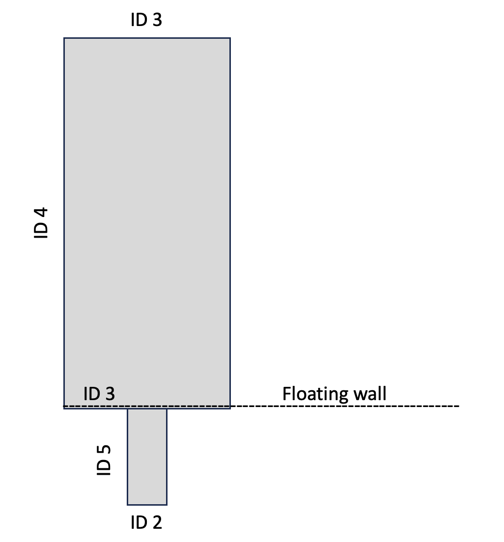
We place a floating wall at the bottom of the cylinder, which is at \(z = 0\), to ensure that the particles remain within the cylinder during the loading step.
subsection floating walls
  set number of floating walls = 1
  subsection wall 0
    set point on wall = 0., 0., 0.
    set normal vector = 0., 0., 1.
    set start time = 0
    set end time   = 999
  end
end
Running the DEM Simulation#
Assuming that the lethe-particles executable is within your path, the simulation can be launched in parallel as follows:
Note
Running the packing should take approximately 10 minutes on 8 cores.
After the particles have been packed inside the bed, we can move on to the fluid-particles simulation.
CFD-DEM Parameter File#
The CFD-DEM simulation is carried out using the packed bed previously generated. Here we will focus on the modified section as well. We recommend visiting the Unresolved CFD-DEM Parameters Guide for a detailed description.
Simulation Control#
The simulation is run for 5 seconds with a time step of 0.001 seconds. The time scheme and setting for output is shown as follows:
subsection simulation control
  set method               = bdf2
  set number mesh adapt    = 0
  set output frequency     = 50
  set time end             = 5
  set time step            = 0.001
end
Boundary Conditions#
Regarding the boundary conditions, we apply slip boundary condition to the wall, a uniform Dirichlet boundary condition at the bottom of the small channel, and outlet to the top of the cylinder. The following schematic figure describes the ID of each boundary and the positon of the floating wall.

We set the inlet velocity to 2.5 m/s, and the background velocity to 0.5 m/s on the bottom of the cylinder as in the previous spouted bed example. The value of beta on the outlet boundary was set to 100, which is relatively high, to stabilize the simulation and prevent backflow.
subsection boundary conditions
  set time dependent = false
  set number         = 5

  subsection bc 0 #outlet
    set id   = 3
    set type = outlet
    set beta = 100
  end

  subsection bc 1 #inlet
    set id   = 2
    set type = function
    subsection u
      set Function expression = 0
    end
    subsection v
      set Function expression = 0
    end
    subsection w
      set Function expression = 2.5
    end
  end

  subsection bc 2 #wall
    set id = 6
    set type = slip
  end

  subsection bc 3 #channel_wall
    set id = 5
    set type = slip
  end

  subsection bc 4   #bed_wall_bottom
    set id   = 4
    set type = function
    subsection u
      set Function expression = 0
    end
    subsection v
      set Function expression = 0
    end
    subsection w
      see Function expression = 0.5
    end
  end
end
CFD-DEM#
Here, we enable grad-div stabilization, and take the time derivative of the void fraction into account.
subsection cfd-dem
  set grad div                      = true
  set void fraction time derivative = true
  set drag force                    = true
  set buoyancy force                = true
  set shear force                   = true
  set pressure force                = true
  set saffman lift force            = false
  set drag model                    = rong
  set post processing               = true
  set coupling frequency            = 100
  set implicit stabilization        = true
  set grad-div length scale         = 0.26
  set vans model                    = modelA
end
We set the grad-div length stabilization parameter to 0.26, which is the diameter of the geometry. This parameter should be the same length as the characteristic length of the flow. For more detail, please refer to CFD-DEM parameters. Also, the additional sections for the CFD-DEM simulations is the void fraction subsection. This subsections is described in detail in the Void Fraction.
Running the CFD-DEM Simulation#
The simulation is run using the lethe-fluid-particles application. Assuming that the lethe-fluid-particles executable is within your path, the simulation can be launched as per the following command:
Note
Running the packing should take approximately 5 days on 8 cores.
Results#
We briefly discuss the results that can be obtained from this example here.
Total Pressure Drop#
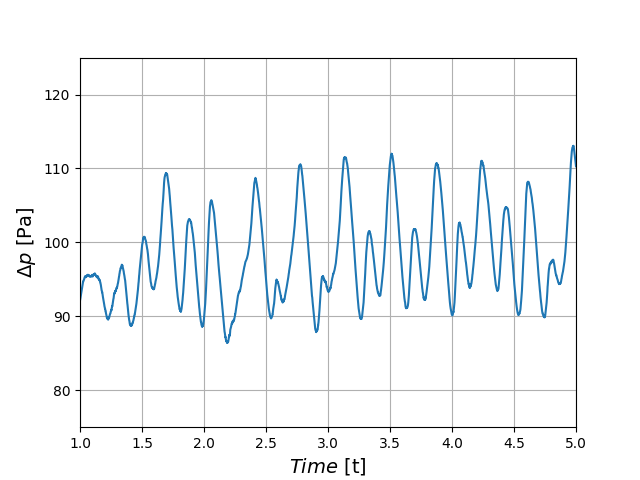
The following plot illustrates the variation of pressure drop from 1 second to 5 seconds. We can see the pressure oscillation which is caused by the bubbly state of the spouted bed.

Visualization#
In the following animation, the bubbly flow can be observed on the right side. the color of the particles represents their IDs, allowing for the visualization of the mixing. On the left side, we show the fluid velocity field.