3D Mixer with Pitched-Blade Turbine Impeller Using Composite Sharp-Immersed Boundary#
The mixing of stirred tanks is a common chemical engineering problem that can be tackled through immersed boundary simulation. This example, a variation of Mixer with Pitched-Blade Turbine Impeller Using Nitsche Immersed Boundary, illustrates how the transient flow in a stirred-tank can be simulated by Lethe using the Sharp-Immersed Boundary formulation with a composite shape.
Features#
Solvers:
lethe-fluid-sharpTransient problem
Rotating complex solid modeled with the sharp immersed boundary method
Files Used in this Example#
Both files mentioned below are located in the example’s folder (examples/sharp-immersed-boundary/3d-composite-mixer-with-pbt-impeller).
Composite geometry file:
impeller.compositeParameter file:
mixer.prm
Description of the Case#
In this example, we simulate a mixer using a PBT impeller through the usage of Sharp-Immersed boundaries. The shape of the impeller is defined by a composition of basic shapes.
Creation of the Composite Shape File#
The shape is created in two steps inspired by the GMSH syntax.
Basic shape definitions. Shapes are defined with different parameters: shape ID, shape type, arguments, position, and orientation.
Boolean operations definitions. Operations are defined by: operation ID, operation type, shape 1 ID, shape 2 ID.
Shapes and boolean operations each have an ID, and boolean operations can reference previous operations to build upon them.
The impeller.composite file contains these instructions.
Note
.composite files can contain comments after # on a line.
shapes
0;        cylinder;                   0.025:0.375;              0:0:0.125 ; 0:0:0
1;        cylinder;                0.05:0.0416666;          0:0:-0.208333 ; 0:0:0
2; hyper rectangle; 0.083333333:0.00625:0.0416666; 0.08333333:0:-0.208333 ; 0.7853981:0:0
3; hyper rectangle; 0.00625:0.083333333:0.0416666;  0:0.08333333:-0.208333; 0:0.7853981:0
4; hyper rectangle; 0.083333333:0.00625:0.0416666;-0.08333333:0:-0.208333 ; -0.7853981:0:0
5; hyper rectangle; 0.00625:0.083333333:0.0416666;0:-0.08333333:-0.208333 ; 0:-0.7853981:0
operations
6; union     ; 0:1
7; union     ; 6:2
8; union     ; 7:3
9; union     ; 8:4
10; union    ; 9:5
Line-by-line:
shapes: introduces the shapes section.0; cylinder; 0.025:0.375; 0:0:0.125 ; 0:0:0: defines a cylinder, with ID equal to 0. Its radius is 0.025 and its half-length 0.375. Its z position is 0.125 and its orientation is default (aligned with Z axis).2; hyper rectangle; 0.083333333:0.00625:0.0416666;0.08333333:0:-0.208333 ; 0.7853981:0:0: defines a hyper rectangle, with ID equal to 1. Its has half-lengths of 0.083, 0.00625, and 0.0417 in X, Y, and Z directions, respectively, in its own referential. Its center is at 0.083, 0, and -0.208 in the global referential and it is rotated by 0.787 radians around the X axis.The other shapes are defined in a similar fashion and are assigned IDs 1, 3, 4, and 5.
operations: introduces the operations section.6; union; 0:1: defines an intermediate shape that is the union of shapes 0 and 1, and assigns it the ID 6.The next operations build iteratively on this intermediate shape.
The result of the last defined operation is considered the definitive shape to be used for simulation, regardless of its ID number.
For more detail on the the definition of the shape see: Sharp-Immersed-Boundary and Simple Plane Model From Composite.
Parameter File#
Definition of the Shape and its Motion#
The section defining each parameter for the particles has certain requirements:
length ratiodefines the length used to apply the immersed boundaries through interpolation. It should stay as low as possible, but above1.typeandshape argumentsare used to declare that the shape is acompositeand that its data is located inimpeller.composite.integrate motionis set tofalse. This way, the solid only moves according to the prescribedorientationand angular velocityomega(the alternative being the integration of particle movement from forces).
subsection particles
  set number of particles                     = 1
  set assemble Navier-Stokes inside particles = false
  subsection extrapolation function
    set stencil order = 2
    set length ratio  = 3
  end
  subsection local mesh refinement
    set initial refinement                = 3
    set refine mesh inside radius factor  = 0.0
    set refine mesh outside radius factor = 1.1
  end
  subsection output
    set enable extra sharp interface vtu output field = true
  end
  subsection particle info 0
    subsection position
      set Function expression = 0;0;0
    end
    subsection velocity
      set Function expression = 0;0;0
    end
    subsection orientation
      set Function expression = -1*2*pi*t;pi/2;0
    end
    subsection omega
      set Function expression = -1*2*pi;0;0
    end
    set type            = composite
    set shape arguments = impeller.composite
  end
end
Boundary Conditions#
Because the interpolation of the velocity field at the surface of a moving particle is not guaranteed to be divergence-free, it is necessary to have at least one boundary condition that is weakly imposed to ensure the system of equations is well-posed. For this purpose, a function weak type of boundary is used.
Two aspects need special consideration:
function weakis a variation offunction. It is used to weakly impose a Dirichlet boundary condition, and it is necessary when usinglethe-fluid-sharp.betahas to be defined. It is a Nitsche penalization parameter that enforces more strongly the boundary condition when it increases (see Nitsche Immersed Boundary).
subsection boundary conditions
  set number = 3
  subsection bc 0
    set id   = 0
    set type = noslip
  end
  subsection bc 1
    set id   = 1
    set type = noslip
  end
  subsection bc 2
    set id   = 2
    set type = function weak
    set beta = 1
    subsection u
      set Function expression = 0
    end
    subsection v
      set Function expression = 0
    end
    subsection w
      set Function expression = 0
    end
  end
end
Results#
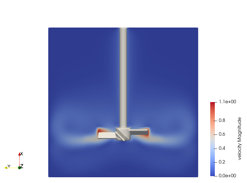
The velocity field obtained with this example is similar to the one obtained with the Nitsche immersed boundary.

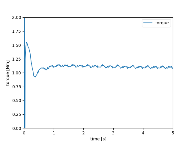
Using meter and second as the length and time units and assuming a fluid density of \(1000 \left(\frac{\text{kg}}{\text{m}^3}\right)\) produce the following torque on impeller:
